PetroChina Hangzhou Research Institute of Geology, Hangzhou 310023, China
2.
Qingdao Institute of Marine Geology, China Geological Survey, Qingdao 266071, China
3.
Laboratory of Marine Mineral Resources, Pilot National Laboratory for Marine Science and Technology (Qingdao), Qingdao 266237, China
4.
China National Oil and Gas Exploration and Development Corporation, Beijing 100034, China
5.
Institute of Oceanology, Chinese Academy of Sciences, Qingdao 266071, China
Funds:
The China-ASEAN Maritime Cooperation Fund Project under contract No. 12120100500017001; the National Natural Science Foundation of China under contract Nos 42076219, 92055211 and 42006067.
Analysis of 3D seismic data and well log data from the Rovuma Basin in East Africa reveals the presence of a late Eocene channel-lobe complex on its slope. The first two channels, denoted as channel-1 and channel-2, are initiated within a topographic low on the slope but come to a premature end when they are blocked by a topographic high in the northwest region of the basin. New channels migrate southeastward from channel-1 to channel-6 due to the region’s sufficient sediment supply and stripping caused by bottom currents. The primary factors controlling the development of the channel complex include its initial paleo-topographic of seafloor, the property of gravity flows, the direction of the bottom current, and the stacking and expansion of its levees. The transition zone from channel to lobe can also be clearly identified from seismic sections by its pond-shaped structure. At a certain point, thest systems record a transiton from erosive features to sedimentary features, and record a transition from a confined environment to an open environment. Channels and lobes can be differentiated by their morphologies: thick slump-debris flows are partly developed under channel sand sheets, whereas these slump-debris flows are not very well developed in lobes. Well log responses also record different characteristics between channels and lobes. The interpreted shale volume throughout the main channel records a box-shaped curve, thereby implying that confined channel complexes record high energy currents and abundant sand supply, whereas the interpreted shale volume throughout the lobe records an upward-fining shape curve, thereby indicating the presence of a reduced-energy current in a relatively open environment. Within the Rovuma Basin of East Africa, the average width of the Rovuma shelf is less than 10 km, the width of the slope is only approximately 40 km, and the slope gradient is 2°–4°. Due to this steep slope gradient, the sand-rich top sheet within the channel also likely contributes to the straight feature of the channel system. It is currently unclear whether the bottom current has any effect on its sinuosity.
Rovuma Basin and Mozambique Basin are two major basins in East Africa. Mozambique Basin has been the focus of numerous geological investigations (Flores, 1973; Förster, 1975; Salman and Abdula, 1995), while previous studies focusing on the Rovuma Basin are mainly limited to those of Flores (1973), Civitelli (1988), Afonsky et al. (1990), Salman and Abdula (1995), and Mahanjane and Franke (2014). However, large discoveries of deep-water oil and gas have been continuously reported in the Rovuma Basin since 2009, with an estimated potential of 150 trillion cubic feet, confirming that the deep-water regions of this basin represent a prolific gas province (Salazar et al., 2013). The discoveries in Rovuma Basin also revealed the huge exploration potential of deep-water gravity sediment systems (Palermo et al., 2014, 2015). Although recent hydrocarbon exploration is successful in Rovuma Basin, there is still lack of the descriptions for the channel-lobe complex, especially for the late Eocene deep-water sediment system.
In this paper, a giant late Eocene deep-water sand-rich channel-lobe system is revealed and described by seismic data, which show some attractive features, such as whole view covering feeder channels to lobes, lateral migration channels and asymmetric levees. Meanwhile, the study distinguished the differential channel and lobe deposits by both seismic data and well logs. Furthermore, the study proposed an evolution pattern for late Eocene deep-water sediment system, which considered the interaction of hybrid flows. Therefore, the goal of this paper is to contribute a case study of lateral migrating straight channel system, and corresponding lobe system near equatorial regions, to analyze sediment processes forming the unique giant sediment system.
2.
Geological setting
Rovuma Basin is an elongated, NNW–SSE-striking, wedge-shaped continental margin basin, which occupies part of the East African passive margin (Fig. 1). The basin is approximately 250 km wide in the north, including both onshore and offshore, and narrowed down to a width of 20 km in the south. The basin is bounded by the Mozambique fold belt to the west and the Querimbas Graben and Davie Fracture Zone to the east (Figs 1 and 2), where the water depth reaches approximately 3 000 m.
Figure
1.
Regional geological setting of the Rovuma Basin: a. location of the study area; b. location of the Rovuma Basin. Dotted line denotes the fold-thrust zone determined by Mahanjane and Franke (2014).
Figure
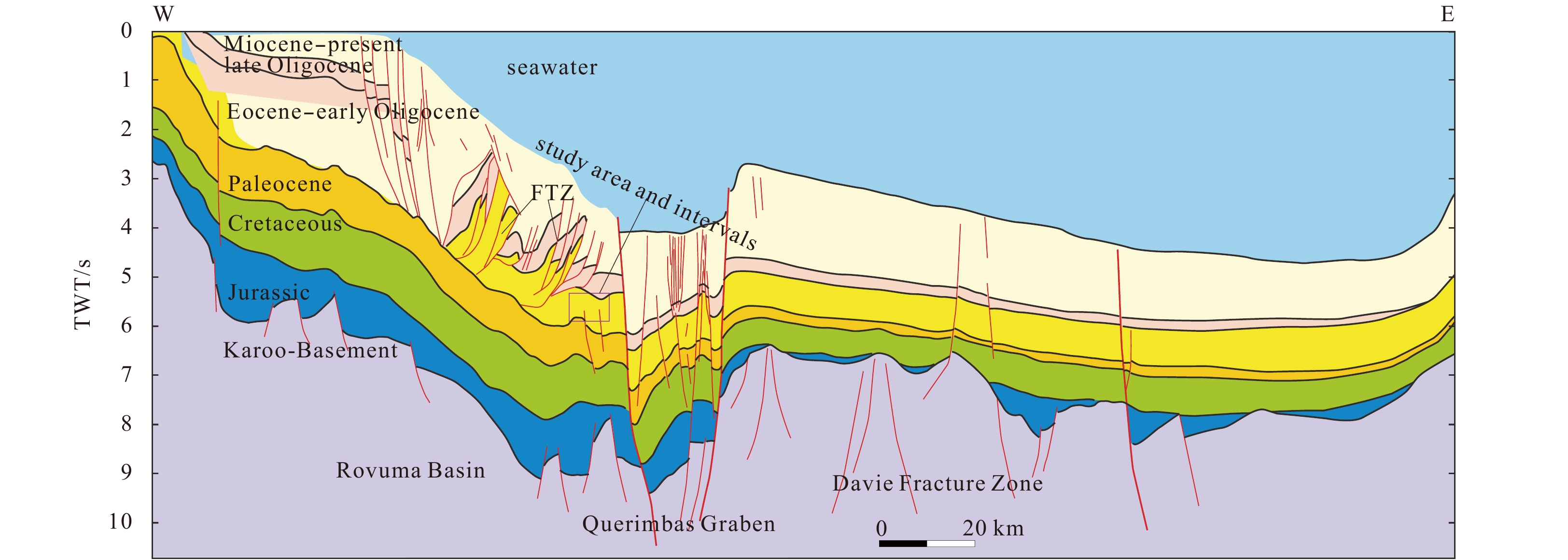
2.
Regional stratigraphic cross section of Rovuma Basin. The section elongated along the west–east direction shows the structures of the Rovuma Basin, Querimbas Graben and Davie Fracture Zone, and the evolution of late Gondwana to post-Gondwana stratigraphic sequences. The study area and intervals are marked by a pink box in this section. FTZ: the fold and thrust zone. TWT: two-way-travel time. For the location of the profile, please see Fig. 1. For locations of submarine channels, please see Figs 4 and 7.
The study area, which covers an approximate area of 1 080 km2, is situated 30 km offshore from the southeast region of the Rovuma River Mouth, 60 km offshore from the northeast region of the Mesalo River Mouth of Mozambique (Fig. 1). Its present water depth lies between 1 200 and 2 500 m, thus classifying it as a deep-water setting.
Sedimentary sequence of Rovuma Basin is bound to the west and south by Mozambique Belt (Pinna, 1995), which recorded four phases of tectonic evolution during middle Jurassic (Hancox et al., 2002). According to Rabinowitz et al. (1983), thermochronological and structural data from basement rocks proximal to the Rovuma Basin margin indicate that only a narrow zone was affected by rifting (Daszinnies et al., 2009; Emmel et al., 2011), which is typical for a trans-tensional rift basin.
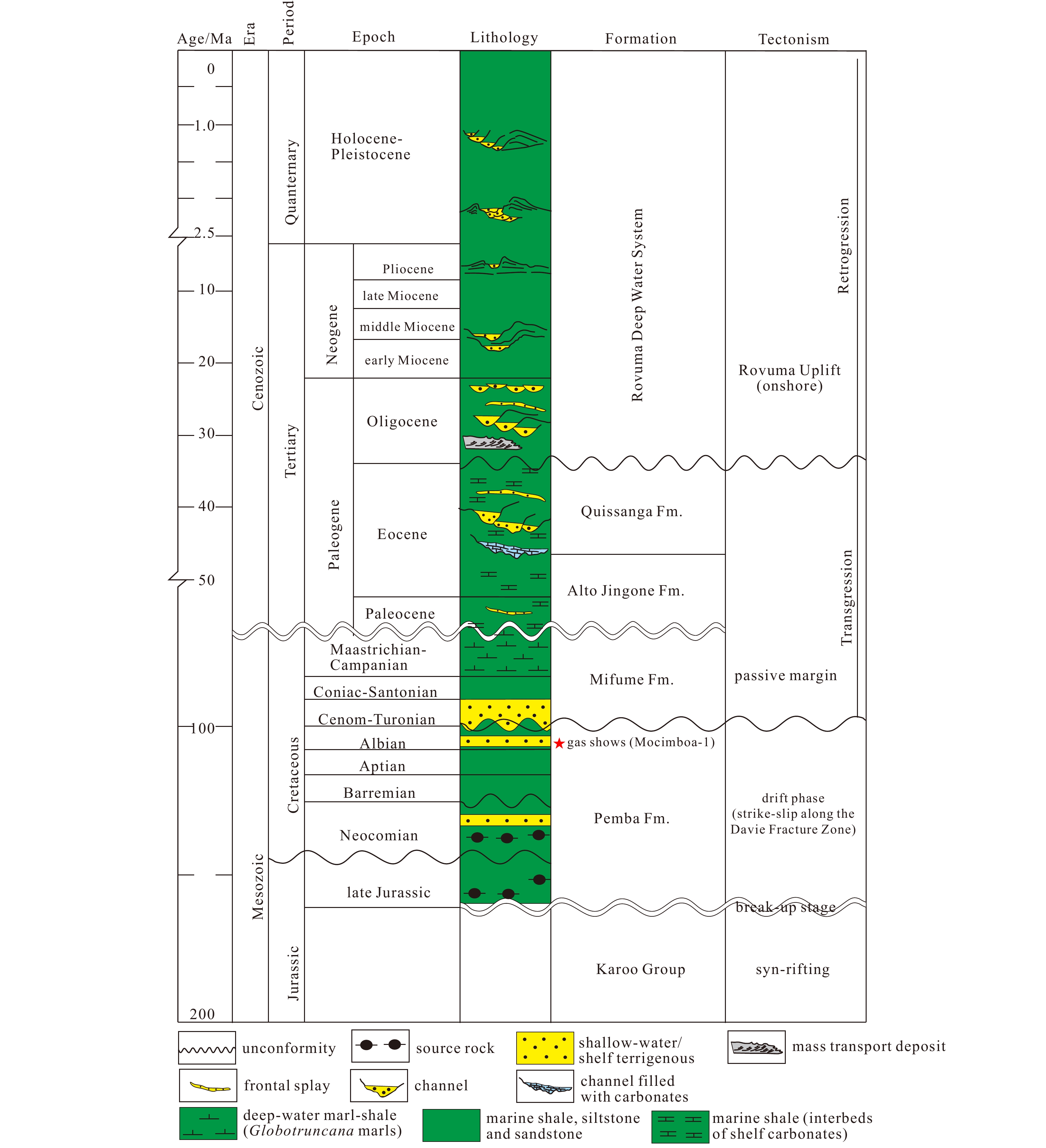
The lithostratigraphy of the Rovuma Basin is divided into two parts by an unconformity produced by the breakup of Gondwana (Raillard, 1990). Beneath this unconformity is late Triassic to middle Jurassic Karoo sediment, mostly comprise intracontinental syn-rift lacustrine shales and sandstones, with the maximum thickness of approximately 10 km (Salman and Abdula, 1995; Key et al., 2008; Smelror et al., 2008; Salazar et al., 2013; Zhou et al., 2013; Mahanjane and Franke, 2014). Karoo Group is likely absent in Rovuma Basin due to uplift and erosion (Key et al., 2008), Pemba formation represents the first sequence of late Gondwana in the Rovuma Basin instead (Fig. 3).
Pemba Formation, has been dated to Tithonian to Albian age, is mainly composed of continental clastic sandstones, marine shale siltstones and sandstones deposited in a transitional-shallow marine environment during a drifting period, with offshore thickness of up to several thousand meters (Key et al., 2008).
Late Cretaceous marine transgression event, following the Pemba Formation, produced a slope and deep-water setting, resulting in the accumulation of the Mifume Formation, which was dominated by gray marls, mudstones and calcareous sandstones, intersected by limestone (Key et al., 2008; Sapri et al., 2013).
The deep-water gravity system began to develop in study area from Paleocene (Figs 2 and 3), which is dominated by lobe complexes. From Paleocene to Eocene, the Alto Jingone and Quissanga Formations were deposited in a transgression setting (Dayang et al., 2013), represented by shelf carbonates containing interbeds of calcareous sandstone and marls (Key et al., 2008; Smelror et al., 2008). The sediment was clay dominated in offshore areas (Salman and Abdula, 1995), with the maximum continental marginal deposition in Eocene (Nairn et al., 1991). The thickness of the post-Mifume Formation sediments increased rapidly eastward, from less than a few hundred meters to approximately 3 000 m.
The deep-water gravity system continued developing in study area, which exhibit progradation features. The channel complexes appeared in Eocene (Figs 2 and 3), with the lobe complex deposited in more distal areas. At the end of Eocene, Rovuma deltaic complex was initiated during the transition from transgression to retrogression. Thick, eastward-prograding wedge of Cenozoic fluvial deltaic deposition unconformably overlaid Paleocene–Eocene successions (Key et al., 2008; Salman and Abdula, 1995). The origin of the delta formation is likely the regional uplift of East Africa, which can potentially be linked to doming in the Oligocene (Key et al., 2008) or an earlier stage in the Lutetian or Eocene (Roberts et al., 2012), prior to the formation of the East African Rift. The uplift in East Africa modified continental drainage patterns and contributed significantly to the development of the deltaic complex (Roberts et al., 2012). The late Eocene deep-water gravity system in Rovuma basin is the target sediment system in this study (Figs 2 and 3), which is also proved to be giant gas reservoir with good property.
3.
Data and methods
The 3D seismic data used in this study cover an approximately 30 km×36 km sub-volume of data acquired in 2010 (Fig. 3). Eight parallel Sercel Seal cables, each 6 000 m in length, produced a total of 960 channels in group intervals of 6.25 m, and achieved a recording length of 10 s two-way-travel-time (TWT). The bin size of these 3D seismic data is 6.25 m×25 m, within the 48th nominal fold. Seismic profiles were performed with bin sizes of 12.5 m and 25 m in the inline and crossline directions, respectively. The dominant frequency in the interval of interest (4–5 s TWT of this study) was 30 Hz, which is equivalent to a vertical resolution of approximately 20 m, based on an interval velocity of 2 000 m/s.
A synthetic seismogram was generated to determine the top and base of the Eocene and Oligocene intervals in the seismic section. The stratigraphy of the top and base of the Eocene and Oligocene was seismically interpreted using a density of 50 in-lines and 25 cross-lines (producing a grid approximately 625 m×625 m in size), which were then interpolated to a size of 12.2 m×25 m to obtain a continuous and smooth surfaces. The surfaces were used for creating seismic attributes map in plan view (Fig. 4).
Figure
4.
Seafloor topography is extracted from the 3D seismic volume; submarine channels are marked by channels F–J. For the location of the 3D survey, please see Fig. 1. The line AA′, line BB′, line CC′ and line DD′ are seismic cross-sections.
Figure
5.
Seismic sections and well logs of deep-water sedimentation in study area. High amplitude reflectors (HARs) segments are discontinuously distributed on an amplitude blanking background within Eocene and Oligocene layers. HARs and the fold and thrust zones (FTZs) are denoted by the arrows and dotted line, respectively. The red boxes in seismic sections indicate the logging intervals, which are zoomed-in in right figures (d and e). Submarine channels are marked by the letters G, H, I and J. Vsh represents interpreted shale volume. For the locations of line AA′ (a), line BB′ (b), and line CC′ (c) and locations of submarine channels G, H, I and J, please see Fig. 4.
Seismic stratigraphic analysis (Payton, 1977) has been used to estimate the different lithologies and intervals. Root mean square (RMS) seismic attribute has been used for illustrating the plan view of sediment system, as the RMS amplitude indicates amplitude anomalies, which is useful for tracking the lithologic changes such as sandstone and mudstone.
Borehole data from the offshore Well-1 and Well-2 are also used in this study. Well-1 and Well-2 penetrated a target channel and lobe, respectively, which provided wire logs for this study, including gamma (GR), interpreted shale volume (Vsh), and porosity. Both Well-1 and Well-2 were systematically cored at intervals of interest.
4.
Results
4.1
The presence of deep water gravity sediment system
Within the Rovuma Basin of East Africa, the average width of the Rovuma shelf is less than 10 km (Fig. 2), the width of the slope is only approximately 40 km, and the slope gradient is approximately 2°–4°. Seismic data discover the presence of submarine channels on the present seafloor, as marked by letters F–J (Figs 4-6). Figures 5 and 6 demonstrate that a dense series of submarine channels, up to 10 km wide and 220 m deep, occur on the seafloor, elongating from west to east. The width in the upstream, as in west, is greater than in the downstream, as in east. Some of the submarine channels are filled by sediment, which are characterized by high amplitude reflectors (HARs), while some of them lack of sediment fillings (Figs 5 and 6).
Figure
6.
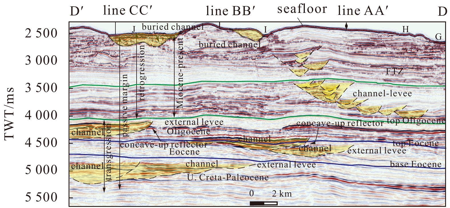
Seismic section across study area, which shows present-day submarine channels and sand-rich paleo-channels from the line DD′. Please note the similarity in both size and shape between the ancient channels and present-day submarine channels, and the concave-up reflectors denoting the sand-rich channel boundary. For the location of line DD′ and the locations of submarine channels J, I, H and G, please see Fig. 4.
The ancient deep-water systems could be obviously recognized in the study area. Both profile view from seismic section and plan view from seismic surface as well as seismic attributes demonstrated the existence of sub-marine channel and lobes, from Paleocene to present seafloor (Figs 5–7). They are characterized by a series of HARs among low amplitude reflections representing surrounding strata (McHargue et al., 2011; Mayall et al., 2010). Similar seismic responses as sand-rich channel and canyon fill elements in other deep-water systems have been recorded, which express discontinuous and HARs with V or U shapes (Wynn et al., 2007; Saller et al., 2004) (Figs 5 and 6). The associated gull-wing-shaped or wedge-shaped low amplitude or transparent seismic reflections indicate the occurrence of levees, which are generally mud-rich deposits (Wynn et al., 2007; Saller et al., 2004) (Figs 5 and 6). The internal reflector geometries of these levees could be divided into several stages, coinciding with the stages of channels, which indicate that they have aggraded, producing higher reliefs while remaining in the same general geographic location (Figs 5 and 6). These lobes are also characterized by HARs in seismic sections, and usually composed of varying proportions of relatively flat reflectors, convex-upward reflectors, and discontinuities, along with concave-up reflectors that are apparently related to channels (Saller et al., 2008) (Fig. 5).
Figure
7.
3D visualization of Root-mean-square (RMS) amplitude attribute of top Eocene sand (time window: top Eocene −10 ms +70 ms TWT), showing the plan view of the distribution of the deep-water channel-lobe complex within the 3D survey area, offshore Rovuma Basin. Six stages of channels are marked by C-1 to C-6, while lobes are marked by lobe-3 to lobe-6. Their outlines are marked by dash lines in different colors. The migration direction is also marked by red dash lines and arrows. The channel-lobe complexes bended to north in the middle stream, then bended to south in the lower stream. They migrated from north to south, from the first stage to the youngest stage. Different stages of channel-lobe complexes are marked. For the location of the 3D survey, please see Fig. 1. For detail stages see Figs 10and 11.
Figure
8.
Seismic sections across deep-water channel complex deposits at different locations from the proximal (c) area to the middle (b) and the distal end (a). C-1–6 and L-1–6 represent channel-1–6 and levee-1–6, respectively. For the locations of profiles EE′, FF′ and GG′, please see Fig. 7. NGR: net to gross ratio; MTD: mass transport deposit.
Regardless of the FTZs, HARs exist even in the formation below the Eocene and above the Oligocene, which are recorded as continuous and stable seismic characteristics, whereas formations between these record discontinuous characteristics (Fig. 5). The earlier sediment system in late Cretaceous–Paleocene showns in Fig. 6 are approximately 10 km wide and 300 m thick. They are roughly the same size and shape as the present-day submarine channel J (Fig. 4).
4.2
Recognition of the late Eocene channel-lobe complexes
4.2.1
Overview from channel to lobe
Seismic attributes demonstrate that the RMS seismic amplitude is the most sensitive attribute reflecting the existence of sand-rich sediments in a deep-water environment. The RMS amplitude attribute map extracted from the 3D seismic volume dataset along the top of the Eocene boundary with a time window of +10 ms −70 ms reveals a planar view of the Eocene deep-water sediment system (Fig. 7). Lower RMS amplitudes (shown in blue) are mainly distributed in the northwestern and southeastern corners of the region, whereas higher RMS amplitudes (shown in red) are mainly confined in the middle (Fig. 7). Clear boundaries exist between lower and higher amplitudes, indicating clear boundaries between deep-water systems and surrounding strata. Integrating the RMS attribute and seismic sections, six channels could be distinguished, which are denoted as channel-1 to channel-6, moving from northwest to southeast (Figs 7 and 8). These six channels are grouped together and almost parallel to each other but contain clear boundaries of low RMS amplitudes between them. Among these six channels, four of them have developed lobes in the termination of them, which are correspondingly marked as lobe-3, lobe-4, lobe-5 and lobe-6 (Figs 7 and 9), whereas lobe-1 and lobe-2 are missing. Parts of channel-1, channel-2, and channel-3 are also missing.
Figure
9.
Seismic section across lobe-6, showing the profile along the gravity flow direction (a) and cross-section profiles from the proximal area (b) to the distal area (c). The purple dash line and arrow denote the thinning direction from the proximal area to the distal end of sedimentary lobe-6. The channel-lobe transition zone shows the position of change from channel to lobe. MTD: mass transport deposit; CLTZ: channel-lobe transition zones. For the locations of profiles HH′, II′ and JJ′, please see Fig. 7.
The sizes of the channels and lobes are relatively similar. Each individual channel is approximately 1–2 km wide and 20–25 km long, and each corresponding lobe is approximately 3–5 km wide and 8–12 km long (Fig. 8). For example, within the 3D survey area, channel-lobe-6 starts in the southwest corner and stretches straight to the northeast; after approximately 10 km, it bends slightly to the north and then again to the northeast. At the transition point from the channel to the lobe, the lobe axis bends to the southeast instead of maintaining the direction of the channel (Fig. 7). The entire channel-lobe complex exhibits a U-shaped pattern, in which its mouth opens to the southeast. Generally, these channels are straight and do not curve in a meandering system (Fig. 7).
RMS amplitude can help to reveal the planar distribution of individual channels or lobes but cannot be used to determine the stacked relationships between individual channels or lobes, which requires the further integration of multiple seismic sections and log data of multiple wells.
4.2.2
Channel-Levee complex
The Eocene channel-lobe complex is composed of six channels, as the channel-1 to channel-6, and four lobes, as lobe-3 to lobe-6. The channels and lobes are spatially and temporally related.
Seismic cross-sections EE′, FF′, and GG′, each is approximately 8 km long, reveal changes in the channel from its upper reaches to its lower reaches (Fig. 8). On seismic profiles, deep-water channel complex deposits in the study area are U- or V-shaped. The lower section of the vertical deep-water channel complex deposits contains low-amplitude, discontinuous and chaotic seismic reflections, whereas the upper part of the section is characterized by high-amplitude, poorly to moderately continuous seismic reflections (Fig. 8). The chaotic reflections in lower part are very thick but become thinner when moving from cross-section EE′, 325 ms TWT (approximately 390 m) to cross-section FF′, 200 ms TWT (approximately 240 m) and to cross-section GG′, 190 ms TWT ( approximately 228 m) (Fig. 8). The thickness of HARs in upper part is relatively thin and becomes thinner moving down course. For example, the thickness of channel-2 moving from cross-section EE′ is 75 ms TWT (approximately 90 m), that of cross-section FF′ is also 75 ms TWT (approximately 90 m), and that of cross-section GG′ is 40 ms TWT (approximately 48 m) (Fig. 8). Across the channel complex section, its thickness pinches out from the axis to the edge, producing a concave-downward shape. Along this channel complex, the cross-section morphologic changes from being U-shaped to V-shaped, likely due to the bending of the course from the northeast direction to a roughly northward direction (Fig. 7).
Well-1 reveals the sediment characteristics of channel sands in study area. The channel sands are characterized by box-shaped and low value GR curve, which is interpreted into sand-rich intervals (Fig. 5). Five box-shaped GR curve intervals are documented in Well-1, recording total thickness of sand-rich intervals of 97 m, as each of them is 32 m, 15 m, 20 m, 10 m and 20 m from upper part to base. The GR curve is nearly straight, yielding a net to gross ratio (NGR) as high as 0.97 (Fig. 5), indicating the presence of an abundant sand supply in a restricted environment. In contrast, the box-shaped of high amplitude in the GR curve reflecting the presence of mud-rich intervals (Fig. 5).
Wedge-shaped levees could be identified in study area, which have developed only on the leeward side, instead of on each side of the channel (Fig. 8). They are represented by transparent, wedge-shaped seismic reflectors laterally distributed in the north side of channel. The levees are thicker close to channels, thinning far away from channels. Six stages of levees could be identified in seismic sections, corresponding with six channels. These aggraded upward and finally buried their channel, before prograding southeastward, migrating and stacking from channel-1 in northwest to channel-6 in southeast (Fig. 8).
The levees are quite large in study area. The thickness of the levee in cross-section DD′ is more than 550 ms TWT, which is approximately 660 m. Cross-section GG′ records a thickness of 350 ms TWT, which corresponds to a thickness of approximately 420 m. The levee extends outside the 3D survey area can reach a width of 30 km (Fig. 8).
4.2.3
Lobe complex
Lobe complex is lobate in plan view and correspond to strong-amplitude, good-continuity, mound-shaped reflection in seismic profiles (Fig. 9). Seismic profile HH′, which is located along the gravity flow direction, demonstrates that the thicknesses of these sedimentary lobes tend to decrease toward their distal direction (Fig. 9a). In cross-section II′, the lobe thickness also decreases toward its margin in a lenticular shape (Fig. 9b). Several small-scale deep-water channel branches can be distinguished on top of these lobes by their uneven surfaces. As these lobes propagate forward, cross-section JJ′ (Fig. 9c) reveals significantly thinned thicknesses and branched lobes. Seismic profiles II′ to JJ′ reflect the transition from the incised lenticular structures of the proximal superimposed deep-water channel branches to the branched layer-crossed structures of the distal lobes. The lobe deposits are composed of relatively flat, continuous and convex-upward reflectors with a thickness of approximately 45 ms in TWT, which corresponds to a thickness of approximately 54 m.
Well-2 reveals the lithologic characteristics in lobe complex (Fig. 5). Within the logging intervals in Well-2, approximately 135 m thick intervals are identified, which is characterized by normal grading sand-rich intervals. Four sharp turns from high to low amplitude in the GR curve, as sharp boundaries, which divide whole lobe complex sediment into four lobe sediment intervals. These four sand-rich lobe sediment intervals record a relatively low NGR of 0.58 (Fig. 5), comparing with NGR of channel sand. The typical pattern of GR curve is the serrated shape of ascending amplitude and high frequency. This pattern as reflecting the normal grading and upward-fining alternative thin beds of fine sandstone, siltstone and mudstone (Fig. 5), indicating the gradualweakening of the current energy, which coincides with the open-front splay environment typical for lobe deposition.
4.2.4
Channel-lobe transition zones
Channel-lobe transition zones (CLTZ) are revealed in seismic section in study area (Fig. 9a). They commonly developed at the canyon/channel mouths, and are associated with a break of slope. CLTZ represented environment transition as well, which implied sediment processes corresponded to the transition between confined to less confined, and then to unconfined environment (Jegou et al., 2008). They are characterized by erosional features, such as scours with hundreds of meters in width and length, and tens of meters in depth (Wynn et al., 2002; Hofstra et al., 2015). In study area, CLTZ exhibits a V-shaped hole (Fig. 9a), reflecting the scour features here. It occupies approximately 1 000 m wide and 60 m deep space (Fig. 9a), without internal seismic reflections. This feature may indicate the sediment bypasses in this zone, exhibited waterfall pond feature, for accepting and accumulating later deposits from the upper reaches.
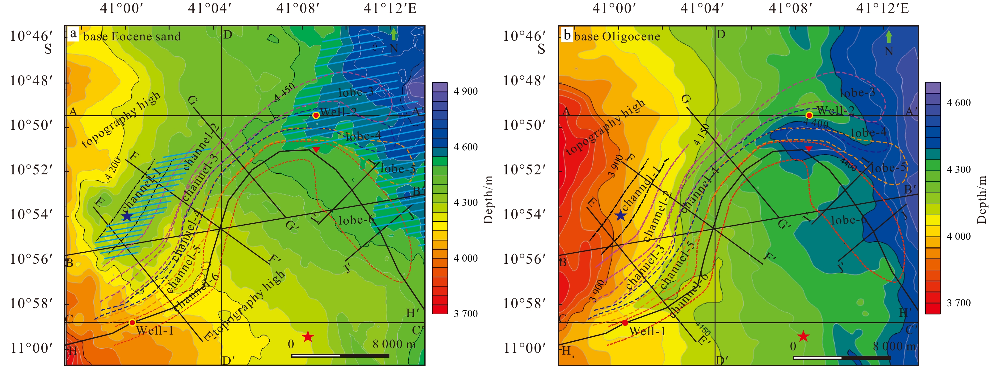
After CLTZ, these turbidity currents may enter an open environment, where they might lose most of their energy and ability to incise a deep channel course and may instead slowly spread out to form a lobe. Near CLTZ, on the topographic map of the base Oligocene, as shown in Fig. 10b, there is an oval-shaped ellipse with long axis, short axis and depth dimensions of 2 000 m, 1 000 m, and 50 m, respectively. To sum up, this topographic low can also serve as a waterfall pond to decrease the gravity flow velocity from the channel to the lobe and can thus also be interpreted as a channel-to-lobe transition point (Fig. 10b).
Figure
10.
Six stages of channel-lobe systems superimposing on seafloor topography extracted from 3D seismic volume data recording environments of channel-lobe complex development from start (a) to finish (b). The blue line shadows on a mark the topographic low at the time of initiation of the channel-lobe complex. Red and blue stars on a and b represent the same site to show changes in topography. The red triangle represents a topography low on b showing the channel-to-lobe transition point.
Systematic core observations and descriptions in previous studies, together with seismic and log data in some cases studies, demonstrated that some submarine channels record nearly the similar lithofacies as submarine lobes (Zhang et al., 2016a). However, more cases revealed that channel fills were generally dominated by thicker and coarser sands or conglomerates deposits, and graded laterally to finer grained sands and silts from channel axis to marginal area. The associated lobe deposits were dominated by individual finer and thinner sediment beds (Normark, 1978; Falivene et al., 2006).
In study area, the well logs, integrating the seismic data, including seismic sections and attributes, reveal the sand-rich sediment in Eocene gravity system (Fig. 5). Both channel and lobe fillings are reflected by high amplitude reflections in seismic sections, and exhibit high amplitude anomalies in RMS attribute map (Figs 7–9). However, precisely seismic and well logs analysis reveals the differential sediment features between channel fillings and lobe fillings.
The deep-water channel vertical filling pattern established by Mayall et al. (2006) indicates that a complete channel facies sequence consists of retention sediments, slump-debris flow deposits, superimposed deep-water channel deposits with high sand-to-shale ratios, and channel deposits with low sand-to-shale ratios, from bottom to top. In study area, the sand-rich channel complexes are reflected by the U-shaped, discontinuous high-amplitude reflectors in seismic sections (Saller et al, 2008) (Figs 5 and 6), while the transparent seismic reflection on the sides of channels are mud-rich external levees (Saller et al., 2004) (Figs 5 and 8). The filling materials in channel complex in study area could be divided into upper part and lower part. The upper part of the section is characterized by high-amplitude, poorly to moderately continuous seismic reflections (Fig. 8), which is proved to be thick massive sandstone (Fig. 5). The lower part of the channel complex deposits, which is not penetrated by drilling wells, exhibits chaotic seismic reflections interbedded with transparent seismic reflections (Fig. 8). They are confined in V- or U- shaped channel complex, and are interpreted into thick slump-debris flow deposits/MTD below the massive sand of the channel complex (Lu et al., 2018; Weimer et al., 2006; Cronin et al., 2005). The thickness of these lower intervals could reach a maximum thickness of 390 m (Fig. 8).
The lobe complex is characterized by relatively more sheet-like high amplitude seismic reflections (Fig. 9). Beside both sides of CLTZ, the seismic reflections are more tabular in lobe complex. Well logs in study area also indicated the different lithofacies between channel fills and lobe deposits. Well-1 located in channel revealed thicker and coarser massive sand than the sandy beds revealed by Well-2, although the gross thickness of sandy beds in Well-2 is thicker. The thickness of channel fill massive sandstone in Well-1 could reach to more than 55 m in single bed, while the single bed of lobe comprising massive sandstone was less than 15 m. Meanwhile, the well logs exhibited more muddy and silty materials in lobe deposits. Well log responses record apparently different characteristics between channels and lobes. The Vsh interpreted from GR throughout the main channel shows a box-shaped curve (Fig. 5), thus demonstrating that confined channel complexes record high energy currents and abundant sand and coarser material supply. Whereas the Vsh log in lobe-4 exhibited a zigzag feature, which records an upward-reducing curve, indicated high content of muddy interbeds and upward-fining and thinning trend, demonstrating the presence of a reduced current energy in a relatively open environment (Fig. 5). These features were also agreed with that channel fill massive sand had high NGR, while lobe deposits had lower NGR.
Moreover, the slump-debris flows are not very well developed in lobes, comparing with the lower part of channel fillings. These features indicate a transition from a confined to an open environment and from a high-energy environment to a low-energy environment. When gravity flows travel to the termination of the deep-water channels, in which both the restrictive environment and the current energy disappear, lobe deposits are formed as a series of branched channel deposits and sand sheets.
5.2
Origin and controlling factors of submarine channel migrations
The genetic mechanisms of deep-water gravity sediment remain controversial and could include slide/slumps, debris flows, high-density turbidity currents, low-density turbidity currents, or hemipelagic deposits (Bouma, 1962; Lowe, 1982; Shanmugam, 1996, 1997, 2003, 2013, 2016), which could impact the productions of sedimentary gravity flows. Active submarine canyons and channels are often zones of coarse sediment bypass, which are also incised and sculpted by erosion; when inactive, significant volumes of both fine-grained and coarse-grained sediment can accumulate within them as a result of various processes (Clark and Pickering, 1996; Prather, 2003; Cronin et al., 2005; McHargue et al., 2011).
The mechanisms generating gravity flows in the study area could have various origins (Mulder et al., 2009). Although no single mechanism can be rejected—particularly seismicity, which is very important in this area (Gutscher et al., 2002; Zitellini et al., 1999)—here, the study assume that the direct connections between the channel-lobe complex and tectonic uplift implied that tectonic activity strongly controls both the feeding and the activity of the studied channel-lobe complex.
The Rovuma delta system represents the source of the giant deep-water sediment system, in which the age of tectonic uplift in this region coincides with the age of the development of the deep-water channel-lobe complex. Well core data reveal that carbonate breccias and calcareous sandstone of the early Eocene deep-water sequence were likely sourced from the shelf and deltaic area, indicating the strong uplift of earlier Eocene strata within this region.
Due to tectonic uplift and falling sea level, the early Eocene shelf carbonates and calcareous sandstones likely collapsed. These carbonate clasts were then transported into the deep-water area by high-energy turbidity currents and debris flows moving throughout the channel complex.
Previous case studies revealed wide range of architectural styles of modern and ancient submarine channels, which were controlled by the behavior of through-channel flows (Clark and Pickering, 1996). Generally, channel systems on relatively gentle slopes are sinuous (Deptuck et al., 2007, 2008), whereas channels on rough and steep slopes are straighter because their high gradient slopes provide higher energy gravity currents that can quickly incise into the paleo-seafloor to form the origin framework of channel systems (Zhang et al., 2016b). The submarine channel developed with straight shape were classified to erosional channels, with contrast with aggradational or depositional channels, which are associated with low sinuosity, steep slopes, coarse-grained turbidity current and small terrestrial drainage basin areas (Clark et al., 1992; Kenyon, 1992; Clark and Pickering, 1996; Kenyon et al., 2002). The descriptions for erosional channels were coincided with the situation of Eocene deep water sediment system in Rovuma Basin. Within the Rovuma Basin in East Africa, the average width of the Rovuma shelf is less than 10 km, the width of the slope is only approximately 40 km, and the slope gradient is approximately 2°–4°. The Rovuma slope is thus relatively short and steep compared to the West African slope, which has a gradient of only 0.1°–0.5°. Additionally, well log and seismic sections reveal that the lithology of the channel is mainly sand, which can be eroded easily, potentially providing another reason for its straight features.
During the development of late Eocene deep-water sediment system, the interaction of hybrid currents may play a significant role. These sediment processes are widely revealed in offshore area in East Africa (Palermo et al., 2014, 2015; Fonnesu, 2013; Fonnesu et al., 2020; Fuhrmann et al., 2020) and South China Sea (Wang et al., 2017). As the North Atlantic Deep Water (NADW) is discovered along the East African margin (Breitzke et al., 2017; Sansom, 2018; Thiéblemont et al., 2019), the rework from the contour current should be considered. The NADW flows from south to north, across the Rovuma Basin, of which direction coincides with the motion of fine-grained sediment. The fine-grained sediment are brought by the NADW, accumulated in the north side of channel complex, building huge lateral levees (Fig. 11), and left with coarser-grained sediment in channels. Although the study propose that the bottom current causes channel migration in this study area, however it is still unknown that this bottom current has any effect on its sinuosity.
Figure
11.
Simplified sketch model showing the development of the late Eocene channel-lobe complex. The different events of turbidity currents came from the west upper slope, transport sandy material to deep water channel and lobe area, while the south-to-north direction bottom current brought the finer material to the north side of these systems, built asymmetric levee in the north part. The levee confined the north margin of channel systems, caused the channels laterally migrated in north-to-south direction.
Channel-levee systems usually developed a long cut-and-fill sedimentary history (Sylvester et al., 2011). Erosional channel generally experienced three sedimentary phases, which were erosion, throughflow and non-deposition phase, deposition phase, and abandonment phase, with repetition of these three phases (Clark and Pickering, 1996). The channel or channel complex was initially formed by erosional process, and then complicated by alternative erosional and depositional processes, accompanying with the development of overbank elements (Sylvester et al., 2011).
Blue stars and red stars are placed on the same site in Figs 10a and b to depict changes in topography before and after the development of the channel-lobe complex. The red star is on the southeast side of the channel complex, and the blue star is on the northwest side of the channel complex; the direction of the bottom current moves from the red star to the blue star. At the red star site, the depth remains stable at 4 250 m; at the blue star site, the depth changes by 400 m, from 4 350 m to 3 950 m, following the development of the channel complex (Fig. 10). Therefore, the study assumes that changes in topography following the development of the channel complex are mainly due to the stacking and expanding of levees.
Typically, the direction of the lobe axis will remain the same as the axis of its feeder channel. However, as shown in Fig. 7, lobe-3 to lobe-6 all bend slightly from the northeast direction to the east or southeast, forming a highly curvature morphology from channel to lobe. And the topographic high on the northwest side of the channel and lobe confined the course of this channel and lobe. As the channel-levee system continued to build a topographic high, especially in the north of Well-2 (Fig. 10b), lobe-5 and lobe-6 had no choice but to bend to the east and southeast. The size and shape of the transition pond from channel to lobe may also have been a factor causing the bending from the channel axis to the lobe axis.
The deeper part of the topographic low is marked by blue lines in Fig. 10a; this represents a suitable location in which lobe development could have been accommodated. Sediment materials likely passed through the feeder channel and naturally poured into this topographic low, spreading out in a lobate shape. As a result, lobe-3, lobe-4 and lobe-5 now occupy and fill the bay-shaped topographic low outlined by the 4 500 m bathymetric contour shown in Fig. 10a.
The paloe-topographic characteristics in study area indicated that the Eocene channel complex was initially defined by the paleo-topographic low area, which expressed “U” or “V” shapes in seismic profiles (Fig. 8). Here the study discusses the late Eocene deep water sediment system was the latest part of this channel complex sequentially developed and evolved in the paloe-topographic low area as a confined environment. The fillings of earlier stage channel complex were characterized by chaotic blank reflectors, partially bearing high amplitude reflectors, which implied MTD and lagging beds in the lower part of channel complex.
In conclusion, the study presents a simplified evolution model for the Eocene deep-water sediment system to delineate the development of the channel-lobe complex (Fig. 11). The first two channels were initiated from a topographic low on the slope but came to a premature end, likely due to the blocking of the topographic high in the northwest (Fig. 10a). Due to the sufficient sediment supply and the stripping of the bottom current, fine-grained particles from turbulent flows produced giant levees exclusively on the northern flanks of these channels (Figs 8 and 10b). As the levees continued to stack upward to form a topographic high and continued to prograde laterally, earlier stage channels were buried by the prograding levee, and later stage channels migrated southeastward from channel-1 to channel-6 (Fig. 11b). Therefore, the main factors controlling the development of the channel complex is those of the initial paleo-topography, the direction of the bottom current, and the stacking and expansion of the levees.
The channel associated lobes expressed relatively small lobate shape, with low relief sheet-like feature in seismic profiles. Meanwhile, the channel system was with low sinuosity and lateral unconfined or lateral semi-confined. These features coincided with the characteristics described as point-source sand-rich submarine fans (Reading and Richards, 1994). However, the channel-lobe system in study area exhibited different features. The major anomaly was the absence of large-scale lobe. From channel-1 to channel-5, there were no noticeable lobes developed in the termination of channels. Until channel-6, the larger-scale lobe feature could be identified in plan view (Figs 7 and 10). According to the well logs and interpretation, the turbidity current probably filled by sandy material, and get much sandy with rework of bottom current. The low-efficiency turbidity currents in this system could not travel far into the basin, and caused the thick sandy deposit in channels. Meanwhile, the fine-grained materials were brought by bottom current to the north levee element, which caused the lack of fine-grained material in turbidity current. Therefore, there were no such abundant sediment materials for deposition of lobes.
6.
Conclusions
Seismic data and well logs reveal the deep-water sediment system in Rovuma Basin. A late Eocene channel-lobe complex is developed on the slope of the Rovuma Basin. Six channels and four related lobes could be identified in this system, which elongated from west to east. The channels migrated from north to south, with asymmetric huge levees laterally developed in the north side of channels. The main factors controlling the development of the channel complex are the initial topographic high, the direction of the bottom current, and the stacking and expansion of the levees.
CLTZ, which indicate the change between confine and unconfined sediment environment, can be clearly identified from seismic sections by a pond-shaped structure. The sediment in channels and lobes exhibits differential features. The presence of thick slump-debris flows developed under massive channel sand sheets differentiates the sediment characteristics within lobes. Meanwhile, massive sandstones in channels imply that high energy currents and abundant sand supply in confined channel complexes. While the lower NGR stacked sandstones in lobes indicate reduced-energy currents in a relatively open environment.
The feature of late Eocene deep-water sediment system should be controlled by the paleo-slope gradient, as well as the property of gravity flows. Meanwhile, the northward flowing NADW may play a significant role in the evolution pattern of late Eocene deep-water sediment system, which controlled the distribution of fine-grained materials. However, it remains unclear whether the bottom current has any effect on the sinuosity of sediment system.
Acknowledgements
We thank the Hangzhou Research Institute of Geology research team and the CNPC International Ltd. Mozambique Company for their contributions. We especially thank the ENI East Africa Company for their discussions and the approval of this publication.
Abreu V, Sullivan M, Pirmez C, et al. 2003. Lateral accretion packages (LAPs): an important reservoir element in deep water sinuous channels. Marine and Petroleum Geology, 20(6–8): 631–648
[2]
Bain H A, Hubbard S M. 2016. Stratigraphic evolution of a long-lived submarine channel system in the Late Cretaceous Nanaimo Group, British Columbia, Canada. Sedimentary Geology, 337: 113–132
[3]
Barnes N E, Normark W R. 1985. Diagnostic parameters for comparing modern submarine fans and ancient turbidite systems. In: Bouma A H, Normark W R, Barnes N E, eds. Submarine Fans and Related Turbidite Systems. New York: Springer-Verlag, 13–14
[4]
Bassias Y. 1992. Petrological and geochemical investigation of rocks from the Davie fracture zone (Mozambique Channel) and some tectonic implications. Journal of African Earth Sciences, 15(3–4): 321–339
[5]
Bird D. 2001. Shear margins: Continent-ocean transform and fracture zone boundaries. The Leading Edge, 20(2): 150–159
[6]
Bouma A H. 1962. Sedimentology of Some Flysch Deposits: A Graphic Approach to Facies Interpretation. Amsterdam: Elsevier
[7]
Bouma A H, Normark W R, Barnes N E. 1985. Submarine Fans and Related Turbidite Systems. New York: Springer
[8]
Bowen A J, Normark W R, Piper D J W. 1984. Modelling of turbidity currents on Navy Submarine Fan, California Continental Borderland. Sedimentology, 31(2): 169–185
[9]
Breitzke M, Wiles E, Krocker R, et al. 2017. Seafloor morphology in the mozambique channel: evidence for long-term persistent bottom-current flow and deep-reaching eddy activity. Marine Geophysical Research, 38(3): 241–269
[10]
Callow R H T, Kneller B, Dykstra M, et al. 2014. Physical, biological, geochemical and sedimentological controls on the ichnology of submarine canyon and slope channel systems. Marine and Petroleum Geology, 54: 144–166
[11]
Civitelli G. 1988. The Meso-Cenozoic sedimentary sequence of the Cabo Delgado Province, Mozambique. Journal of African Earth Sciences, 7(4): 629–639
[12]
Clark J D, Kenyon N H, Pickering K T. 1992. Quantitative analysis of the geometry of submarine channels: Implications for the classification of submarine fans. Geology, 20(7): 633–636
[13]
Clark J D, Pickering K T. 1996. Architectural elements and growth patterns of submarine channels: Application to hydrocarbon exploration. AAPG Bulletin, 80(2): 194–220
[14]
Coffin M F, Rabinowitz P D. 1987. Reconstruction of Madagascar and Africa: Evidence from the Davie Fracture Zone and Western Somali Basin. Journal of Geophysical Research: Solid Earth, 92(B9): 9385–9406
[15]
Coffin M F, Rabinowitz P D. 1992. The Mesozoic East African and Madagascan conjugate continental margins: Stratigraphy and tectonics. In: Watkins J S, Feng C C, McMillen K J, eds. Geology and Geophysics of Continental Margins. AAPG Memoir, 53: 207–240
[16]
Covault J A, Graham S A. 2010. Submarine fans at all sea-level stands: Tectono-morphologic and climatic controls on terrigenous sediment delivery to the deep sea. Geology, 38(10): 939–942
[17]
Covault J A, Normark W R, Romans B W, et al. 2007. Highstand fans in the California borderland: The overlooked deep-water depositional systems. Geology, 35(9): 783–786
[18]
Cronin B T, Çelik H, Hurst A, et al. 2005. Mud prone entrenched deep-water slope channel complexes from the Eocene of Eastern Turkey. In: Hodgson D M, Flint S S, eds. Submarine Slope Systems: Processes and Products. London: The Geological Society of London, 224: 155–180
[19]
Daszinnies M C, Jacobs J, Wartho J A, et al. 2009. Post Pan-African thermo-tectonic evolution of the north Mozambican basement and its implication for the Gondwana rifting. Inferences from 40Ar/39Ar hornblende, biotite and titanite fission-track dating. In: Lisker F, Ventura B, Glasmacher U A, eds. Thermochronological Methods: from Palaeotemperature Constraints to Landscape Evolution Models. London: The Geological Society of London, 324: 261–286
[20]
Deptuck M E, Piper D J W, Savoye B, et al. 2008. Dimensions and architecture of late Pleistocene submarine lobes off the northern margin of East Corsica. Sedimentology, 55(4): 869–898
[21]
Deptuck M E, Sylvester Z, Pirmez C, et al. 2007. Migration-aggradation history and 3-D seismic geomorphology of submarine channels in the Pleistocene Benin-major Canyon, western Niger Delta slope. Marine and Petroleum Geology, 24(6–9): 406–433
[22]
Emmel B, Kumar R, Ueda K, et al. 2011. Thermochronological history of an orogen-passive margin system: An example from northern Mozambique. Tectonics, 30(2): TC2002
[23]
Falivene O, Arbués P, Gardiner A, et al. 2006. Best practice stochastic facies modeling from a channel-fill turbidite sandstone analog (the Quarry outcrop, Eocene Ainsa basin, northeast Spain). AAPG Bulletin, 90(7): 1003–1029
[24]
Flores G M, Blant G T. 1973. The Cretaceous and Tertiary sedimentary basins of Mozambique and Zululand. In: Blan G T, ed. Sedimentary Basins of the African Coasts. Part II. Paris: Association of African Geology Surveys, 81–111
[25]
Fonnesu F. 2013. The Mamba complex supergiant gas discovery (Mozambique): An example of turbidite fans modified by deepwater tractive bottom currents. In: The 12th PESGB/HGS Conference on African E&P. London: PESGB Conferences Ltd.
[26]
Fonnesu M, Palermo D, Galbiati M, et al. 2020. A new world-class deep-water play-type, deposited by the syndepositional interaction of turbidity flows and bottom currents: The giant Eocene Coral Field in northern Mozambique. Marine and Petroleum Geology, 111: 179–201
[27]
Förster R. 1975. The geological history of the sedimentary basin of southern Mozambique, and some aspects of the origin of the Mozambique Channel. Palaeogeography, Palaeoclimatology, Palaeoecology, 17(4): 267–287
[28]
Fuhrmann A, Kane I A, Clare M A, et al. 2020. Hybrid turbidite-drift channel complexes: An integrated multiscale model. Geology, 48(6): 562–568
[29]
Gutscher M A, Malod J, Rehault J P, et al. 2002. Active subduction beneath the Gibraltar arc. In: EGS XXVII General Assembly. Nice: European Geosciences Union
[30]
Hancox P J, Brandt D, Edwards H. 2002. Sequence stratigraphic analysis of the Early Cretaceous Maconde Formation (Rovuma basin), northern Mozambique. Journal of African Earth Sciences, 34(3–4): 291–297
[31]
Hofstra M, Hodgsona D M, Peakall J, et al. 2015. Giant scour-fills in ancient channel-lobe transition zones: Formative processes and depositional architecture. Sedimentary Geology, 329: 98–114
[32]
Jacobs J, Thomas R J. 2004. Himalayan-type indenter-escape tectonics model for the southern part of the Late Neoproterozoic-Early Paleozoic East African–Antarctic orogen. Geology, 32(8): 721–724
[33]
Jegou I, Savoye B, Pirmez C, et al. 2008. Channel-mouth lobe complex of the recent Amazon Fan: The missing piece. Marine Geology, 252(1–2): 62–77
[34]
Kenyon N H. 1992. Deep sea siliciclastic systems: a plan view perspective. In: Sequence Stratigraphy of European Basins. Dijon: CNRS-IFP, 458–459
[35]
Kenyon N H, Klaucke I, Millington J, et al. 2002. Sandy submarine canyon-mouth lobes on the western margin of Corsica and Sardinia, Mediterranean Sea. Marine Geology, 184(1–2): 69–84
[36]
Key R M, Smith R A, Smelror M, et al. 2008. Revised lithostratigraphy of the Mesozoic-Cenozoic succession of the onshore Rovuma Basin, northern coastal Mozambique. South African Journal of Geology, 111(1): 89–108
[37]
Kolla V. 2007. A review of sinuous channel avulsion patterns in some major deep-sea fans and factors controlling them. Marine and Petroleum Geology, 24(6–9): 450–469
[38]
Kolla V, Posamentier H W, Wood L J. 2007. Deep-water and fluvial sinuous channels—Characteristics, similarities and dissimilarities, and modes of formation. Marine and Petroleum Geology, 24(6–9): 388–405
[39]
König M, Jokat W. 2006. The Mesozoic breakup of the Weddell Sea. Journal of Geophysical Research, 111: B12102
[40]
Lewis K B, Pantin H M. 2002. Channel-axis, overbank and drift sediment waves in the southern Hikurangi trough, New Zealand. Marine Geology, 192(1–3): 123–151
[41]
Lin Yu, Wu Shenghe, Wang Xing, et al. 2013. Research on architecture model of deepwater turbidity channel system: a case study of a deepwater research area in Niger Delta Basin, West Africa. Geological Review (in Chinese), 59(3): 510–520
[42]
Lin Yu, Wu Shenghe, Wang Xing, et al. 2014. Research on reservoir architecture models of deep-water turbidite lobes. Natural Gas Geoscience (in Chinese), 25(8): 1197–1204
[43]
Lowe D R. 1982. Sediment gravity flows: II, depositional models with special reference to the deposits of high-density turbidity currents. Journal of Sedimentary Research, 52(1): 279–297
[44]
Lu Yintao, Li Wei, Wu Shiguo, et al. 2018. Morphology, architecture, and evolutionary processes of the Zhongjian Canyon between two carbonate platforms, South China Sea. Interpretation, 6(4): SO1–SO15
[45]
Mahanjane E S, Franke D. 2014. The Rovuma Delta deep-water fold-and-thrust belt, offshore Mozambique. Tectonophysics, 614: 91–99
[46]
Mayall M, Jones E, Casey M. 2006. Turbidite channel reservoirs—key elements in facies prediction and effective development. Marine and Petroleum Geology, 23(8): 821–841
[47]
Mayall M, Lonergan L, Bowman A, et al. 2010. The response of turbidite slope channels to growth-induced seabed topography. AAPG Bulletin, 94(7): 1011–1030
[48]
McHargue T, Pyrcz M J, Sullivan M D, et al. 2011. Architecture of turbidite channel systems on the continental slope: Patterns and predictions. Marine and Petroleum Geology, 28(3): 728–743
[49]
Migeon S, Savoye B, Babonneau N, et al. 2004. Processes of sediment-wave construction along the present Zaire deep-sea meandering channel: Role of meanders and flow stripping. Journal of Sedimentary Research, 74(4): 580–598
[50]
Mulder T, Gonthier E, Lecroart P, et al. 2009. Sediment failures and flows in the Gulf of Cadiz (eastern Atlantic). Marine and Petroleum Geology, 26(5): 660–672
[51]
Nairn A E M, Lerche I, Iliffe J E. 1991. Geology, basin analysis, and hydrocarbon potential of Mozambique and the Mozambique Channel. Earth-Science Reviews, 30(1–2): 81–123
[52]
Normark W R. 1970. Growth patterns of deep-sea fans. AAPG Bulletin, 54(11): 2170–2195
[53]
Normark W R. 1978. Fan valleys, channels, and depositional lobes on modern submarine fans: Characters for recognition of sandy turbidite environments. AAPG Bulletin, 62(6): 912–931
[54]
Normark W R, Carlson P R. 2003. Giant submarine canyons: Is size any clue to their importance in the rock record?. In: Chan M A, Archer A W, eds. Extreme depositional environments: Mega End Members in Geologic Time. Special Paper of the Geological Society of America, 370: 175–190
[55]
Normark W R, Piper D J W, Hess G R. 1979. Distributary channels, sand lobes, and mesotopography of Navy Submarine fan, California Borderland, with applications to ancient fan sediments. Sedimentology, 26(6): 749–774
[56]
Normark W R, Piper D J W, Hiscott R N. 1998. Sea level controls on the textural characteristics and depositional architecture of the Hueneme and associated submarine fan systems, Santa Monica Basin, California. Sedimentology, 45(1): 53–70
[57]
Palermo D, Galbiati M, Famiglietti M, et al. 2014. Insights into a new super-giant gas field - sedimentology and reservoir modeling of the coral reservoir complex, offshore northern Mozambique. In: Offshore Technology Conference-Asia. Kuala Lumpur: OTC Asia
[58]
Palermo D, Galbiati M, Mezzapesa D, et al. 2015. Sequence stratigraphy, sedimentology and reservoir modelling of the Coral reservoir, offshore northern Mozambique. In: Offshore Mediterranean Conference and Exhibition. Ravenna: OMC
[59]
Paull C K, Caress D W, Ussler W, et al. 2011. High-resolution bathymetry of the axial channels within Monterey and Soquel submarine canyons, offshore central California. Geosphere, 7(5): 1077–1101
[60]
Payton C E. 1977. Seismic Stratigraphy—Applications to Hydrocarbon Exploration. Tulsa, OK, USA: The American Association of Petroleum Geologists
[61]
Peakall J, Amos K J, Keevil G M, et al. 2007. Flow processes and sedimentation in submarine channel bends. Marine and Petroleum Geology, 24(6–9): 470–486
[62]
Peakall J, Sumner E J. 2015. Submarine channel flow processes and deposits: A process-product perspective. Geomorphology, 244: 95–120
[63]
Peakall J, Wells M G, Cossu R, et al. 2013. Global (latitudinal) variation in submarine channel sinuosity: REPLY. Geology, 41(5): e288
[64]
Pickering K T, Hiscott R N, Hein F J. 1989. Deep Marine Environments: Clastic Sedimentation and Tectonics. London: Unwin Hyman
[65]
Pickering K T, Hiscott R N, Kenyon N H, et al. 1995. Atlas of Deep Water Environments: Architectural Style in Turbidite Systems. Dordrecht: Springer
[66]
Pinna P. 1995. On the dual nature of the Mozambique Belt, Mozambique to Kenya. Journal of African Earth Sciences, 21(3): 477–480
[67]
Posamentier H W. 2003. Depositional elements associated with a basin floor channel-levee system: case study from the Gulf of Mexico. Marine and Petroleum Geology, 20(6–8): 677–690
[68]
Prather B E. 2003. Controls on reservoir distribution, architecture and stratigraphic trapping in slope settings. Marine and Petroleum Geology, 20(6–8): 529–545
[69]
Rabinowitz P D, Coffin M F, Falvey D. 1983. The separation of Madagascar and Africa. Science, 220(4592): 67–69
[70]
Raillard S. 1990. Les marges de L’Afrique de l’est et les zones de fracture associées: Chaine Davie et ride du Mozambique, Champagne MD-60/MACA MO-11 [dissertation]. Paris: Universite Pierre et Marie Curie
[71]
Reading H G, Richards M. 1994. Turbidite systems in deep-water basin margins classified by grain size and feeder system. AAPG Bulletin, 78(5): 792–822
[72]
Reeves C V, de Wit M J, Sahu B K. 2004. Tight reassembly of Gondwana exposes Phanerozoic shears in Africa as global tectonic players. Gondwana Research, 7(1): 7–19
[73]
Reimchen A P, Hubbard S M, Stright L, et al. 2016. Using sea-floor morphometrics to constrain stratigraphic models of sinuous submarine channel systems. Marine and Petroleum Geology, 77: 92–115
[74]
Roberts E M, Stevens N J, O’Connor P M, et al. 2012. Initiation of the western branch of the East African Rift coeval with the eastern branch. Nature Geoscience, 5: 289–294
[75]
Salazar M U, Baker D, Francis M, et al. 2013. Frontier exploration offshore the Zambezi Delta, Mozambique. First Break, 31(6): 135–144
[76]
Saller A, Werner K, Sugiaman F, et al. 2008. Characteristics of Pleistocene deep-water fan lobes and their application to an upper Miocene reservoir model, offshore East Kalimantan, Indonesia. AAPG Bulletin, 92(7): 919–949
[77]
Saller A H, Noah J T, Ruzuar A P, et al. 2004. Linked lowstand delta to basin-floor fan deposition, offshore Indonesia: An analog for deep-water reservoir systems. AAPG Bulletin, 88(1): 21–46
[78]
Salman G, Abdula I. 1995. Development of the Mozambique and Ruvuma sedimentary basins, offshore Mozambique. Sedimentary Geology, 96(1–2): 7–41
[79]
Sansom P. 2018. Hybrid turbidite–contourite systems of the Tanzanian margin. Petroleum Geoscience, 24: 258–276,
[80]
Sapri D H, Mahmud O A, Chen H W W. 2013. Sequence stratigraphic study of Areas 3&6, Rovuma Basin, Mozambique. In: International Petroleum Technology Conference. Beijing: European Association of Geoscientists & Engineers
[81]
Scrutton R A. 1978. Davie fracture zone and the movement of Madagascar. Earth and Planetary Science Letters, 39(1): 84–88
[82]
Shanmugam G. 1996. High-density turbidity currents: Are they sandy debris flows?. Journal of Sedimentary Research, 66(1): 2–10
[83]
Shanmugam G. 1997. The Bouma sequence and the turbidite mind set. Earth-Science Reviews, 42(4): 201–229
[84]
Shanmugam G. 2003. Deep-marine tidal bottom currents and their reworked sands in modern and ancient submarine canyons. Marine and Petroleum Geology, 20(5): 471–491
[85]
Shanmugam G. 2008. The constructive functions of tropical cyclones and tsunamis on deep-water sand deposition during sea level highstand: Implications for petroleum exploration. AAPG Bulletin, 92(4): 443–471
[86]
Shanmugam G. 2013. Modern internal waves and internal tides along oceanic pycnoclines: Challenges and implications for ancient deep-marine baroclinic sands. AAPG Bulletin, 97(5): 799–843
[87]
Shanmugam G. 2016. Submarine fans: A critical retrospective (1950–2015). Journal of Palaeogeography, 5(2): 110–184
[88]
Shanmugam G, Bloch R B, Mitchell S M, et al. 1995. Basin-floor fans in the North Sea: Sequence stratigraphic models vs. sedimentary facies. AAPG Bulletin, 79(4): 477–511
[89]
Shanmugam G, Moiola R J. 1982. Eustatic control of turbidites and winnowed turbidites. Geology, 10(5): 231–235
[90]
Shanmugam G, Moiola R J. 1985. Submarine fan models: Problems and solutions. In: Bouma A H, Normark W R, Barnes N E, eds. Submarine Fans and Related Turbidite Systems. New York: Springer-Verlag, 29–35
[91]
Shanmugam G, Moiola R J. 1995. Reinterpretation of depositional processes in a classic flysch sequence (Pennsylvanian Jackfork Group), Ouachita Mountains, Arkansas and Oklahoma. AAPG Bulletin, 79(5): 672–695
[92]
Shepard F P. 1981. Submarine canyons: Multiple causes and long-time persistence. AAPG Bulletin, 65(6): 1062–1077
[93]
Smelror M, Key R M, Smith R A, et al. 2008. Late Jurassic and cretaceous palynostratigraphy of the onshore Rovuma Basin, Northern Mozambique. Palynology, 32(1): 63–76
[94]
Stow D A V, Mayall M. 2000. Deep-water sedimentary systems: New models for the 21st century. Marine and Petroleum Geology, 17(2): 125–135
[95]
Sylvester Z, Pirmez C, Cantelli A. 2011. A model of submarine channel-levee evolution based on channel trajectories: Implications for stratigraphic architecture. Marine and Petroleum Geology, 28(3): 716–727
[96]
Sylvester Z, Pirmez C, Cantelli A, et al. 2013. Global (latitudinal) variation in submarine channel sinuosity: COMMENT. Geology, 41(5): e287
[97]
Thiéblemont A, Hernández-Molina F J, Miramontes E, et al. 2019. Contourite depositional systems along the Mozambique channel: The interplay between bottom currents and sedimentary processes. Deep Sea Research Part I: Oceanographic Research Papers, 147: 79–99,
[98]
Vail P R, Audemard F, Bowman S A, et al. 1991. The stratigraphic signatures of tectonics, eustacy and sedimentology—an overview. In: Einsele G, Ricken W, Seilacher A, eds. Cycles and Events in Stratigraphy. Berlin: Springer-Verlag, 617–659
[99]
Wang Xingxing, Wang Yingmin, He Min, et al. 2017. Genesis and evolution of the mass transport deposits in the middle segment of the Pearl River canyon, South China Sea: Insights from 3D seismic data. Marine and Petroleum Geology, 88: 555–574
[100]
Weimer P, Link M H. 1991. Seismic Facies and Sedimentary Processes of Submarine Fans and Turbidite Systems. New York: Springer
[101]
Weimer P, Slatt R M, Bouroullec R, et al. 2006. Introduction to the petroleum geology of deepwater setting. AAPG Studies in Geology, 57: 171–175
[102]
Wonham J P, Jayr S, Mougamba R, et al. 2000. 3D sedimentary evolution of a canyon fill (Lower Miocene-age) from the Mandorove Formation, offshore Gabon. Marine and Petroleum Geology, 17(2): 175–197
[103]
Wynn R B, Cronin B T, Peakall J. 2007. Sinuous deep-water channels: Genesis, geometry and architecture. Marine and Petroleum Geology, 24(6–9): 341–387
[104]
Wynn R B, Kenyon N H, Masson D G, et al. 2002. Characterization and recognition of deep-water channel-lobe transition zones. AAPG Bulletin, 86(8): 1441–1462
[105]
Zaragosi S, Auffret G A, Faugères J C, et al. 2000. Physiography and recent sediment distribution of the Celtic Deep-Sea Fan, Bay of Biscay. Marine Geology, 169(1–2): 207–237
[106]
Zhang Jiajia, Wu Shenghe, Fan Ting’en, et al. 2016a. Research on the architecture of submarine-fan lobes in the Niger Delta Basin, offshore West Africa. Journal of Palaeogeography, 5(3): 185–204
[107]
Zhang Lei, Li Zhenhai, Zhang Xuejuan, et al. 2015. Lithofacies classification and development rule of gravity flows deposits. Journal of China University of Petroleum (in Chinese), 39(1): 17–24
[108]
Zhang Wenbiao, Duan Taizhong, Liu Zhiqiang, et al. 2016b. Application of multi-point geostatistics in deep-water turbidity channel simulation: A case study of Plutonio oilfield in Angola. Petroleum Exploration and Development (in Chinese), 43(3): 403–410
[109]
Zhou Zongying, Tao Ye, Li Shujun, et al. 2013. Hydrocarbon potential in the key basins in the East Coast of Africa. Petroleum Exploration and Development, 40(5): 582–591
[110]
Zitellini N, Chierici F, Sartori R, et al. 1999. The tectonic source of the 1755 Lisbon earthquake and tsunami. Annals of Geophysics, 42(1): 49–55
José I. Isola, Fermín I. Palma, Sebastían Y. Principi, et al. Morphology and evolution of a modern mixed (turbidite-contourite) depositional system associated with deeply-incised submarine canyons in the Patagonian Continental Margin. Marine Geology, 2025, 480: 107476. doi:10.1016/j.margeo.2025.107476
2.
Haozhe Ma, Xiwu Luan, Thanuja D. Raveendrasinghe, et al. Tectonic influence on the evolutionary dynamics of deep-water channel systems along the active accretionary prism margin in the Rakhine Basin, Myanmar: A high-resolution 3d seismic analysis. Geomorphology, 2024, 458: 109263. doi:10.1016/j.geomorph.2024.109263
3.
Mei Chen, Shenghe Wu, Ruifeng Wang, et al. Sedimentary architecture of submarine lobes affected by bottom currents: Insights from the Rovuma Basin offshore East Africa. Basin Research, 2024, 36(1) doi:10.1111/bre.12829
4.
Jianqiang Wang, Jie Liang, Qingfang Zhao, et al. Characteristics of Deepwater Oil and Gas Distribution along the Silk Road and Their Controlling Factors. Water, 2024, 16(2): 240. doi:10.3390/w16020240
5.
Yufeng Li, Renhai Pu, Gongcheng Zhang, et al. New-type pliocene channel depositional systems resulting from turbidity flows obliquely interacting with contour currents: A novel case study from the southern Qiongdongnan basin, northern South China Sea. Marine and Petroleum Geology, 2023, 147: 105982. doi:10.1016/j.marpetgeo.2022.105982
6.
Rachel A. Sabuni. Petroleum systems and hydrocarbon potential of the Ruvuma Basin, Tanzania. Geoenergy Science and Engineering, 2023, 223: 211588. doi:10.1016/j.geoen.2023.211588
7.
Yintao Lu, Weimin Ran, Xiaoyong Xu, et al. Linear polygonal faults initiated Gully system around the margin slope of middle Miocene carbonate platform in the Northwest South China sea. Marine and Petroleum Geology, 2023, 147: 106022. doi:10.1016/j.marpetgeo.2022.106022
8.
Yintao Lu, Buqing Shi, Xiwu Luan, et al. Fine-grained deep-water turbidite gas reservoirs in upper Bengal Fan. Marine and Petroleum Geology, 2023, 158: 106547. doi:10.1016/j.marpetgeo.2023.106547
9.
Yufeng Li, Renhai Pu, Gongcheng Zhang, et al. Architecture, controlling factors and evolution history of unidirectionally upstream-migrating turbidite channels: A case study from southern Qiongdongnan Basin, northern South China Sea. Marine and Petroleum Geology, 2022, 141: 105706. doi:10.1016/j.marpetgeo.2022.105706
Figure 1. Regional geological setting of the Rovuma Basin: a. location of the study area; b. location of the Rovuma Basin. Dotted line denotes the fold-thrust zone determined by Mahanjane and Franke (2014).
Figure 2. Regional stratigraphic cross section of Rovuma Basin. The section elongated along the west–east direction shows the structures of the Rovuma Basin, Querimbas Graben and Davie Fracture Zone, and the evolution of late Gondwana to post-Gondwana stratigraphic sequences. The study area and intervals are marked by a pink box in this section. FTZ: the fold and thrust zone. TWT: two-way-travel time. For the location of the profile, please see Fig. 1. For locations of submarine channels, please see Figs 4 and 7.
Figure 4. Seafloor topography is extracted from the 3D seismic volume; submarine channels are marked by channels F–J. For the location of the 3D survey, please see Fig. 1. The line AA′, line BB′, line CC′ and line DD′ are seismic cross-sections.
Figure 5. Seismic sections and well logs of deep-water sedimentation in study area. High amplitude reflectors (HARs) segments are discontinuously distributed on an amplitude blanking background within Eocene and Oligocene layers. HARs and the fold and thrust zones (FTZs) are denoted by the arrows and dotted line, respectively. The red boxes in seismic sections indicate the logging intervals, which are zoomed-in in right figures (d and e). Submarine channels are marked by the letters G, H, I and J. Vsh represents interpreted shale volume. For the locations of line AA′ (a), line BB′ (b), and line CC′ (c) and locations of submarine channels G, H, I and J, please see Fig. 4.
Figure 6. Seismic section across study area, which shows present-day submarine channels and sand-rich paleo-channels from the line DD′. Please note the similarity in both size and shape between the ancient channels and present-day submarine channels, and the concave-up reflectors denoting the sand-rich channel boundary. For the location of line DD′ and the locations of submarine channels J, I, H and G, please see Fig. 4.
Figure 7. 3D visualization of Root-mean-square (RMS) amplitude attribute of top Eocene sand (time window: top Eocene −10 ms +70 ms TWT), showing the plan view of the distribution of the deep-water channel-lobe complex within the 3D survey area, offshore Rovuma Basin. Six stages of channels are marked by C-1 to C-6, while lobes are marked by lobe-3 to lobe-6. Their outlines are marked by dash lines in different colors. The migration direction is also marked by red dash lines and arrows. The channel-lobe complexes bended to north in the middle stream, then bended to south in the lower stream. They migrated from north to south, from the first stage to the youngest stage. Different stages of channel-lobe complexes are marked. For the location of the 3D survey, please see Fig. 1. For detail stages see Figs 10and 11.
Figure 8. Seismic sections across deep-water channel complex deposits at different locations from the proximal (c) area to the middle (b) and the distal end (a). C-1–6 and L-1–6 represent channel-1–6 and levee-1–6, respectively. For the locations of profiles EE′, FF′ and GG′, please see Fig. 7. NGR: net to gross ratio; MTD: mass transport deposit.
Figure 9. Seismic section across lobe-6, showing the profile along the gravity flow direction (a) and cross-section profiles from the proximal area (b) to the distal area (c). The purple dash line and arrow denote the thinning direction from the proximal area to the distal end of sedimentary lobe-6. The channel-lobe transition zone shows the position of change from channel to lobe. MTD: mass transport deposit; CLTZ: channel-lobe transition zones. For the locations of profiles HH′, II′ and JJ′, please see Fig. 7.
Figure 10. Six stages of channel-lobe systems superimposing on seafloor topography extracted from 3D seismic volume data recording environments of channel-lobe complex development from start (a) to finish (b). The blue line shadows on a mark the topographic low at the time of initiation of the channel-lobe complex. Red and blue stars on a and b represent the same site to show changes in topography. The red triangle represents a topography low on b showing the channel-to-lobe transition point.
Figure 11. Simplified sketch model showing the development of the late Eocene channel-lobe complex. The different events of turbidity currents came from the west upper slope, transport sandy material to deep water channel and lobe area, while the south-to-north direction bottom current brought the finer material to the north side of these systems, built asymmetric levee in the north part. The levee confined the north margin of channel systems, caused the channels laterally migrated in north-to-south direction.


 DownLoad:


 DownLoad:


